
There is a major difference when manufacturing anisotropic radially magnetized rings and arcs compared to manufacturing diametrically magnetized rings and arcs. It is only possible to achieve radially aligned and magnetized anisotropic rings and arcs in fully dense sintered NdFeB. Additionally, a dedicated press tool and magnetizing fixture are needed, as well as requiring a limited physical envelope (max OD 85mm). However, other true radial magnetization patternst can be achieved in all isotropic magnet materials by using both sintered and bonded structures.
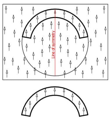
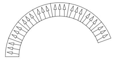
As a general rule, most permanent magnets are produced with one single direction of magnetization. In these cases, the lines of flux within the magnetic material are parallel, such as in with axially magnetized block, rod, and disc magnets. Arcs, meanwhile, are cut from blocks of manufactured magnetic material. In figure 1, the standard direction of magnetization is reflected by the arrows.
When a block of magnetic material is manufactured, the direction of magnetization is fixed into the structure. This is because the block is pressed to shape in the presence of an external magnetic field. In this method (which is standard practice), the external magnetic field is produced by a solenoid surrounding the block. By using this method, the cut arc will share the same direction of magnetization as the original block.
Looking again at figure 1, the arc has been cut in a way that the direction of the magnet’s magnetization is parallel to the magnet’s line of symmetry. This is defined as “diametrically magnetized.” As such, the standard direction of magnetization within such cut arcs is diametrically magnetized.
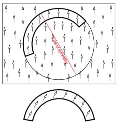
Should an arc be rotated around by a defined angle, the direction of magnetization would be rotated around by the same defined angle, as illustrated in figure 2. In designs such as Hallbach Arrays, this feature proves to be particularly useful.
True Radial Arcs and Ring Magnets
True radial arcs and ring magnets are typically much more difficult to produce. Typically, they either require tooling to produce, or it may not be possible to produce them at all due to the system’s size requirements. In the case of low volume prototypes, as well as circumstances where the size needed is larger than what the tooling can produce, it is best to utilize a high number of very small angle arcs in order to effectively create a radial field in ring magnets or in large arcs. Just as before, when one is considering the system as a whole, it is much more difficult to assemble 360 magnets at a 1 degree arc compared to producing a single ring.
As an alternative to a pure field created by 1 degree arcs, larger diametrically magnetized arcs can be used instead to replicate a radially magnetized arc or ring. Hence, the name “Pseudo Radial” is used, as there is now a major difference in the ultimate magnet field generated.
Making Pseudo Radial Arcs and Rings from Large Angle Diametrically Magnetized Arcs
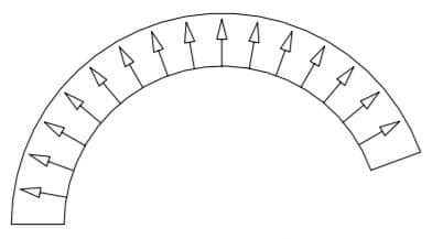
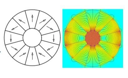
When using diametrically magnetized arc segments of a large angle, the magnetic pattern in the competed ring and arc begins to mimic a desired radial pattern. The effect may be cruder if large angle arcs are used, but the benefit to this method is that assembly time is relatively fast. An example, featuring forty degree arcs, can be seen in figure 4.
Making Pseudo Radial Arcs and Rings from Small Angle Diametrically Magnetized Arcs
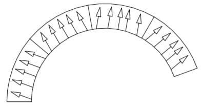
When using diametrically magnetized arc segments of small angle, the magnetic pattern in the completed ring and arc begins to mimic the desired radial pattern more closely. It is possible to improve this effect if even smaller angle arcs are used, though this has the downside of increasing the assembly time. Despite not producing a perfect radial pattern, the finished arc still meets the specification requirements for the application. In figure 5, twenty degree arcs are illustrated. Should a pure radial array be required, it is possible to improve the pseudo-radial magnetic wave-shape even further by stacking multiple rings axially with each ring being rotated relative to the next.
Special Use of Arc Magnets: The Halbach Array
A Halbach Array can be produced when using arcs where the direction of magnetization is set to different angles. This results in a homogenous, highly uniform magnetic field in the air gap. As another benefit, the field strength in the air gap can be very large.
Conclusion
Bunting-DuBois has extensive knowledge in the design and manufacture of custom magnets and magnetic assemblies. For more information, please contact us today.